Description
4~20mA current transmitter working principle
In the industrial field, the use of an instrumentation amplifier to complete the signal conditioning and long line transmission, will produce the following problems: first, because the transmitted signal is a voltage signal, the transmission line will be subject to noise interference; second, the distribution resistance of the transmission line will produce voltage drop; third, how to provide the operating voltage of the instrumentation amplifier in the field is also a problem.
In order to solve the above problems and avoid the influence of the relevant noise, we use current to transmit the signal, because the current is not sensitive to noise. 4 to 20mA current loop is used 4ma to indicate the zero signal, 20mA to indicate the full scale of the signal, while the signal below 4mA above 20mA is used for the alarm of various faults.
There are two types of 4~20mA current transmitters: 2-wire and 3-wire. When the monitoring system needs to drive the field actuators such as valves through long lines, the three-wire system transmitter is generally used, where the xtr is located at the system end of the monitoring, and the power is supplied directly from the system to the xtr, and the power supply is the third line other than the two current transmission lines. Two-wire system is xtr and sensor is located at the field end, due to the existence of field power supply problems, generally the receiving end of the current loop using 4 ~ 20mA to the remote xtr power supply, through the 4 ~ 20mA to reflect the size of the signal.
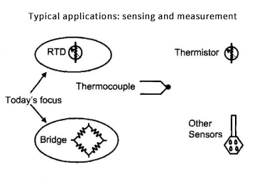
Typical applications for 4 to 20mA products are sensing and measurement applications, see Figure 1. there are many types of sensors in industrial sites that can be converted to 4 to 20mA current signals, ti has some convenient transmitter chips for rtd and bridge. Because it's transmitter chips contain common functional circuits such as voltage excitation sources, current excitation streams, voltage regulators, and instrumentation amplifiers, it is easy to convert many sensor signals to 4-20mA signals.

Most applications of bridge sensors are for measuring pressure. In a practical circuit, if a Wheatstone bridge has a resistance of 2k on each arm, then its equivalent resistance is 2k when viewed from either the excitation voltage side or the differential output side. When no pressure is applied, the bridge is balanced and the output voltage is 0. When pressure is applied, the bridge is unbalanced and a differential voltage is generated, and the differential voltage reflects the magnitude of the pressure.
Fullness and hue are two of the main technical specifications of pressure sensors, and all sensors used in the real world have a certain degree of nonlinearity in that their output voltage varies with temperature. The output voltage does not vary linearly with temperature, and both fullness and hue have this property.
4-20mA sensor signal conditioning solution
4~20mA current loop in the structure consists of two parts, namely transmitter and receiver, the transmitter is generally located at the field side, sensor side or module side, while the receiver is generally at the plc and computer side, it is generally in the controller.
Two-wire 4-20mA circuit application, the working power and signal share a common wire, the working power is provided by the receiving end. In order to avoid the 50/60hz frequency interference, the current is used to transmit the signal. Two-wire scheme requires consideration of the main issues: determine the number of receivers used, when there are multiple receivers, it will require the transmitter to have a lower operating supply voltage. Another consideration is to reduce the voltage drop of the loop current at the receiving end.
The design of a 2-wire solution requires consideration of:
(1) the number of receivers in the circuit loop: more receivers will require a lower operating voltage for the transmitter.
(2) the necessary operating voltage of the transmitter to have a margin.
(3) Decide whether the excitation method of the sensor is voltage or current.
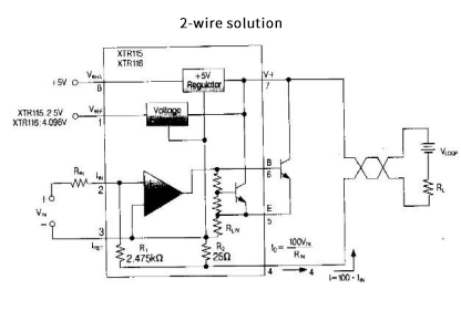
Figure 2 shows a 2-wire solution with voltage regulation and reference circuitry provided by it. The xtr115/116 is a precision signal converter for 4 to 20mA signals, and it contains a 5v voltage regulator circuit that can supply power to external circuits. A precision on-chip reference voltage can be used for voltage biasing or sensor excitation.

The 3-wire 4-20mA circuit is designed to provide operating power from the transmitter side, and to avoid 50/60hz frequency interference, current is used to transmit the signal. xtr regulator and the field load share a common ground connection. The program design requires consideration of:
(1) The number of receivers in the current loop.
(2) More receivers require a higher operating voltage for the transmitter.
(3) to ensure the necessary operating voltage of the transmitter, and should have a certain amount of margin.
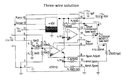
The xtr110 is a precision voltage-to-current converter for analog signal transfer, which can convert input voltages of 0 to 5V or 0 to 10V directly to output signals of 4 to 20mA, 0 to 20mA, and 5 to 25mA. xtr110 contains a precision resistor network to accommodate different input and output requirements. A 10V voltage reference can be used to drive external circuits.

Calibration of 4-20mA
Conventional 4~20mA calibration requires special fixture fixing, special laser or manual resistor adjustment, and the adjustment is mutual, requiring a process of testing, adjusting, re-testing and re-adjusting, with a limited number and range of adjustments. Electronics and sensors are not easy to adjust.
Modern digital 4 to 20mA calibration, which allows the electronics and sensors to be adjusted after the package; can be calculated by computer to simplify the numerical adjustment of the correction coefficient; can have an unlimited number of adjustments, and has a good resolution and a wide range of adjustments; adjustment process does not exist mutual influence; electronics and sensors can be easily adjusted.
The xtr108 is a solution provided by ti to correct 4 to 20mA. It has a current reference of 480 a, it provides rtd nonlinear correction without the need for an external adjustable resistor. xtr108 has the following features:
(1) has a sensor linearization circuit.
(2) Digital correction. The xtr108 can be set directly through the spi interface, and the eeprom can be programmed directly through the spi interface.
(3) Automatic zero-stabilized programmable gain application amplifier with a gain range of 6.26 to 400 times.
(4) The resolution of the programmable current for rtd excitation is 1.54 a.
(5) Calibration parameters are stored in an external eeprom.
(6) Programmable over-range and under-range outputs.
In addition, it offers a digital calibration solution for bridge sensors, the pga309, which is a programmable analog signal conditioner designed for pressure bridge sensors. It simulates the amplifier sensing signal and provides digital correction of the tone voltage and full voltage, which provides long-term stability by avoiding manual adjustment and converts the output voltage signal to a 4-20ma output.


