1. Introduction
Due to the rapid development of mechanical and structural design in recent years, more and more vibration problems have arisen accordingly, and accurate measurement of vibration and shock has become very important. A large number of vibration sensors are used in vibration and shock test measurements. The structure of the vibration sensor is suitable or not, the main parameters are accurate or not, directly related to the reliability and accuracy of the final measurement results. As the sensitivity of vibration sensors will change after a period of time, such as the aging of the piezoelectric material will reduce the sensitivity by 2% to 5% per year. Therefore, it is necessary to calibrate the vibration sensor regularly, which is the most important means to ensure the reliability of the test results.
Piezoelectric acceleration sensor sensitivity, frequency range and dynamic range, volume and mass is relatively small, suitable for the current advanced measurement and analysis equipment requirements, but the more widely used is the open-loop manual acceleration sensor calibration method, open-loop control without feedback information, simple structure and low cost, but the system is susceptible to external interference, control accuracy is relatively low, the output error can not be However, the system is susceptible to external disturbances, the control accuracy is low, and the output error cannot be compensated; manual calibration requires constant adjustment of the signal output and is complicated to operate.In order to overcome the defects of the open-loop manual calibration method, this paper will investigate the closed-loop automatic calibration method of piezoelectric acceleration sensors, in order to provide guidance for the calibration and calibration of piezoelectric acceleration sensors. The paper will use the standard vibration controller of Hangzhou Yiheng Technology Co.
2. Sensor calibration protocols and calibration content
According to the "National Metrological Calibration Procedure of the People's Republic of China JJG 233-2008", there are many items that need to be calibrated for acceleration sensors, among which the most important and the most concerned by users are the sensitivity amplitude, frequency response characteristics and sensitivity amplitude linearity of acceleration sensors.
(1) Sensitivity amplitude
Sensor sensitivity is an important indicator of the static characteristics of the sensor. The static characteristics of the sensor is the output-input relationship when the measured value is in a
stable state. Sensor sensitivity is the ratio of the output increment Δy of the sensor to the input increment Δx that causes the output increment.
(2) Sensitivity frequency response
Frequency response characteristic is a major dynamic characteristic of the sensor. Dynamic characteristics of the sensor is the response characteristics of its output to the time-varying
input; when the measured change over time, is a function of time, the output of the sensor is also a function of time, the relationship between the dynamic characteristics to be expressed.
The response characteristics of the sensor to a sinusoidal input signal, known as the frequency response characteristics. Frequency response characteristics of the calibration methods are
continuous scanning method, point-by-point comparison method, random FFT comparison method.
(3) Sensitivity amplitude linearity
According to the dynamic range of the sensor to be calibrated, select 7~14 points (including the maximum and minimum acceleration) in the specified acceleration range, calibrate the
sensitivity of the sensor to be calibrated, and draw the amplitude linearity curve.
3. Sensor calibration method
For the calibration and calibration methods of accelerometers, absolute and comparative methods are commonly used [3]. The absolute calibration method refers to the method of determining the accelerometer sensitivity by using the basic and derived units of the measured physical quantity. The calibrated sensor is fixed on the calibration shaker, and the amplitude of the shaker is measured directly with a laser interferometer, and then compared with the output of the calibrated sensor to determine the sensitivity of the calibrated sensor, which is the absolute calibration method with laser interferometer, and the calibration error is 0.5%~1%. The absolute method can also be used to measure the frequency response of the sensor.This method has high operational and environmental requirements, as well as high equipment requirements. The comparative calibration method, also known as the back-to-back comparative calibration method, involves mounting the calibrated transducer and the standard transducer, which has been rigorously calibrated by the national metrology department, back-to-back (or carefully side-by-side) in the center of the calibration shaker table and calibrating them at a reference frequency (160 Hz or 80 Hz) and a reference acceleration (100 m/ s2 or 10 m/s2). The ratio of the electrical output of the standard sensor to the acceleration value is the reference sensitivity. Since the calibrated sensor and the standard sensor are mounted back-to-back and are subjected to the same sinusoidal excitation amplitude, the ratio of their electrical outputs is the ratio of their sensitivities.
3.1 Back-to-back direct comparison method
The calibrated transducer and the standard transducer are rigidly connected back-to-back and mounted at the center of the standard shaker table (standard transducer at the bottom and calibrated transducer at the top), and the parameters of sensitivity, amplitude linearity and frequency curve of the calibrated transducer are calculated by comparison.
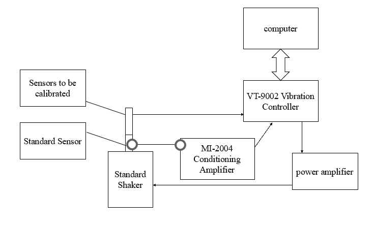
As can be seen from the above figure, the sensitivity of the calibrated sensor is related to the standard sensor system (including the standard charge amplifier and transducer), the shaker and the measurement instrument. These factors contribute a large fraction of its calibration uncertainty rating. Therefore, to reduce the calibration uncertainty of the sensor, the influence of these factors needs to be reduced or eliminated.
4. System function
(1) Calibration of various types of charge, IEPE (ICP), piezoelectric acceleration sensors or magnetoelectric velocity sensors can be calibrated.
(2) Can quickly and accurately complete the sensor sensitivity, frequency response and amplitude linearity calibration.
(3)It can meet the requirements of national standard GB/T 20485.21-2007 (ISO 16063-21:2003) and calibrate the sensor by back-to-back comparison method; it can be calibrated by
alternative method and store or import the test data of sensitivity, amplitude linearity and frequency response of the reference sensor to the working sensor.
(4) Sweep sine method, step sine method and FFT method can be used for frequency response calibration.
(5) Can define the sweep sine spectrum and sweep rate; can define the step sine frequency point and magnitude; can define the FFT amplitude, sampling frequency, points, frequency
range.
(6) Can automatically generate reports, including sensitivity values, frequency response curves, amplitude linearity curves.
5. System features
(1) high precision: the control system has high precision and high dynamic range, the uncertainty of the calibration system depends only on the uncertainty of the power amplifier and
shaker or shaker.
(2) Automatic: friendly graphical interface with real-time display function, the user can set all the test process independently, and through the computer control can automatically
complete the test, real-time monitoring, self-diagnosis and intelligent process.
(3) Combination of control and calibration: Not only can the shaker's vibration control be completed, but also the calibration results of the transducer can be calculated and plotted.
(4) Superior marker function: can add single cursor, double cursor, can read X1, Y1, X2, Y2 values of the cursor location, can add harmonic cursor, and has automatic wave peak and
trough capture function.
(5) Automatic report generation: After the test is completed, the system can generate a detailed WORD test report, including the amplitude linearity and frequency response characteristics
curve.
6. Summary
Sensor calibration and calibration system quickly and accurately calculate the sensitivity of the sensor being calibrated, amplitude linearity, draw frequency response characteristic curve, and automatically generate calibration reports, greatly improving the efficiency of the sensor calibration and calibration work. The system has been widely used in metrology institutes, vibration research laboratories, sensor manufacturers and so on.


