Ⅰ、Analysis of requirements
According to the test requirements of the pressure measurement system, the working conditions of the system are from -55℃ to +100℃. There are 768 pressure measurement channels, and the channels with different ranges are: There were 64 channels in ±5psi, 256 channels in ±15psi, 128 channels in 50psi, 64 channels in 100psi, 128 channels in 250psi, 64 channels in 500psi, 64 channels in 750psi, and 768 channels in total.
Ⅱ、Introduction to the Program
According to the characteristics of range distribution, we use FDS (Flight Data System) System combined with 8 DTC-64HD and 16 NetScanner System 9216 to complete the overall pressure measurement, and the overall test accuracy of the system is ±0.05%FS. Due to the large temperature span of the working condition, to ensure the normal operation of the equipment at low temperature -55℃, we use a special heating tank combined with heat insulation material temperature control unit to achieve the normal operation of the high and low temperature environment for the FDS system, 9216 system and DTC-64HD. Detailed descriptions are given in Sections III and IV.
Ⅲ、FDS(Flight Data System) system
FDS(Flight Data System) system is a set of integrated dual data processor and control unit system, the system will be analog circuit design and digital temperature compensation (DTC) technology integration, so that the product without online full range calibration can maintain the best accuracy. The FDS system can be connected to eight ESP pressure scanners to achieve 512 channels of pressure measurement. The FDS system hosts an advanced architecture that integrates a dual embedded microprocessor and innovative scanner addressing logic to achieve the maximum throughput requirements offered by the electronic pressure scanner.
When the power is unexpectedly repowered, "Live@Power up" mode can automatically return to the data acquisition mode by using the stored scanner configuration, greatly reducing the initialization time, and the engineering data packets collected by the system are directly transmitted to the user's data recording hardware or the host computer through UDP datagram.
After the switch is closed, the automatic zero correction technology and digital temperature compensation technology reduce the zero drift and temperature error to the greatest extent.
PSI Utility Software allows users to configure parameters, calibrate the system, acquire data, record data, and analyze data. It also provides convenient program development support, allowing users to send and receive specific programming commands.
The connection required for system operation is extremely simple and is connected to the FDS Initium host using a 9IFC module and 9082 cable, providing a convenient interface for power regulation, hardware triggering and Ethernet communication. The electrical connection to the ESP pressure scanner is achieved using a PSCB cable, and a typical block diagram of the system connection is shown in Figure 1.
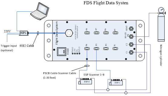
Figure 1 Example FDS system configuration
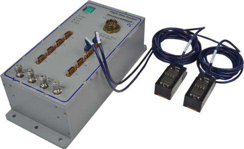
3.1 FDS Initium system host
The FDS Initium host supports 512 pressure channels; The test accuracy was ±0.05%FS. The measurement resolution was 0.003% FS. The total thermal error was ±0.002%FS/℃. The sampling frequency was 650Hz/ channel when all 8 channels were connected to the ESP-32HD scanner. The operating temperature range of the host is 0 to 70℃, and the storage temperature range of the host is 0 to 80℃. Automatically set 10/100 Base-T Ethernet interface; The A/D resolution is 18 bits; Size 301.5mm×133.3mm×92mm (length × width × height), weight 3.63kg.
FDS host temperature control unit can ensure that the host can work normally in the temperature range of -55℃ to 100℃.
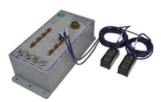
FIG. 2 FDS Flight Data System System
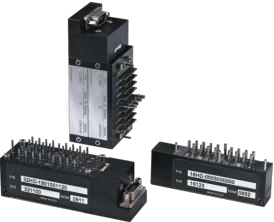
3.2 ESP-64HD miniature pressure scanner
The ESP-64HD miniature electronic pressure scanner module consists of a series of silicon piezoresistive pressure sensors. The accompanying sensor is mounted on a common hybrid ceramic substrate using patented technology to maximize long-term stability. Each pressure sensor on the scanner is equipped with a separate temperature sensor, the pressure sensing mode is differential pressure, and there are two operating modes of calibration and operation.
The ESP-64HD pressure scanner supports 64 pressure input channels. The scan rate was 70,000 Hz; The operating temperature of the scanner is -25℃~+80℃ (100℃ optional), and the storage temperature is -25℃~+100℃; Weight of 143g; With digital temperature compensation function; With blow out function; The scanner dimensions are 80mm long, 33mm wide and 28.6mm high.
This scheme uses 1 DTC-64HD with a range of ±5psid, 4 DTC-64HD with a range of -12psid~+15psid, 2 DTC-64HD with a range of 50psid, and 1 DTC-64HD with a range of 100psid, a total of 8 sets with 512 channels.
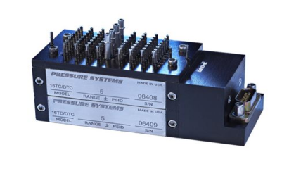
Figure 3 The ESP-64HD miniature pressure scanner
3.3 Scanner heater unit
The ESP Heater Chambers is a heater unit for low temperature environments. It can effectively ensure that the ESP is in the operating temperature range of -25 ° C to +80 ° C, and the lowest can be applied to -55 ° C. It can reduce the influence of temperature on the ESP pressure scanner (non-DTC series ESP) by 10 times. The factory default setting temperature is 40℃, and the user can set the expected temperature in the range of 0℃~+80℃ according to the working conditions. The internal thermal overload protection circuit ensures that the heater will not overheat.
The heater is powered by 28VDC, the maximum operating current is 1.5A, and the power supply is two-wire system. Heater size: Heater size of ESP-64HD: length 115.57mm x width 43.18mm x height 49.53mm, weight 192g.
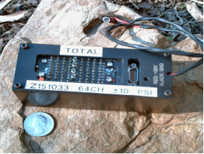
Figure 4 ESP heater unit
3.4 FDS-HCU host heating control unit
FDS host heating temperature control Unit FDS-HCU (Heater Contol Unit) adopts light weight, good insulation polyformaldehyde resin shell, internal heating tank and phase change energy storage material + composite heat insulation material several parts.
This combination of heat storage and heat insulation scheme in the low temperature environment, will execute the heat storage material release heat + heat insulation material preservation process; In a high temperature environment, the process of insulation material isolating external heat + heat storage material absorbing heat will be carried out.
When the ambient temperature continues to decrease (-55℃) and the system is not powered, firstly, when the internal temperature of FDS-HCU is lower than the phase change point of the phase change heat storage material, the phase change material begins to release heat, slowing down the temperature reduction trend in the control unit. Secondly, the composite insulation material will effectively isolate the heat radiation and heat convection inside the heating unit and the external environment. The heat conduction process is greatly slowed down to ensure that the temperature gradient inside FDS-HCU is maintained within a reasonable range within a certain time (6 hours), and the equipment cannot be used because of the low ambient temperature.
When the system is in a high temperature environment (100℃), first, the composite insulation material will effectively isolate the heat radiation and heat convection inside the heating unit and the external environment, which will greatly slow down the heat conduction process. Second, if the internal temperature of FDS-HCU is higher than the phase change point of the phase change heat storage material, the phase change material will begin to absorb heat, slowing down the temperature rising trend in the control unit. These two processes will effectively ensure that the temperature gradient inside FDS-HCU is maintained within a reasonable range within a certain time (8 hours) to ensure the normal operation of the equipment.
In the case of providing power to the FDS-HCU heating control unit, when the ambient temperature continues to decrease and the temperature in the heating control unit is lower than the preset temperature, the heating tank starts heating (the preset temperature point is adjustable). When the temperature in the heating tank reaches the preset temperature, the heating is stopped. Phase change materials and heat insulation materials can effectively ensure the slow change of temperature. In the low temperature environment, the FDS-HCU was warmed up for 10 minutes before each use of the FDS host, and then the pressure measurement operation was started.
FDS-HCU host heating control unit adopts 28VDC power supply, maximum working current is 1.8A, two-wire power supply, structure diagram is shown in Figure 5, temperature control unit size: length 400mm× width 160mm× height 160mm.
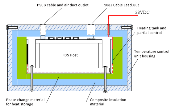
FIG. 5 FDS host heating control unit structure diagram
3.5 Scanner Interface
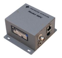
The 9IFC scanner interface provides power and communication to the FDS Initium host, DC power and hardware trigger inputs to the user, and an Ethernet interface for full-duplex TCP/UDP communication. The input voltage is 220VAC; 10/100 Base-T Ethernet interface; Hardware trigger interface options; The size was 88.9×88.9×50.8mm (length × width × height).
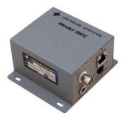
Figure 6 The 9IFC scanner interface
3.6 Interface Connector
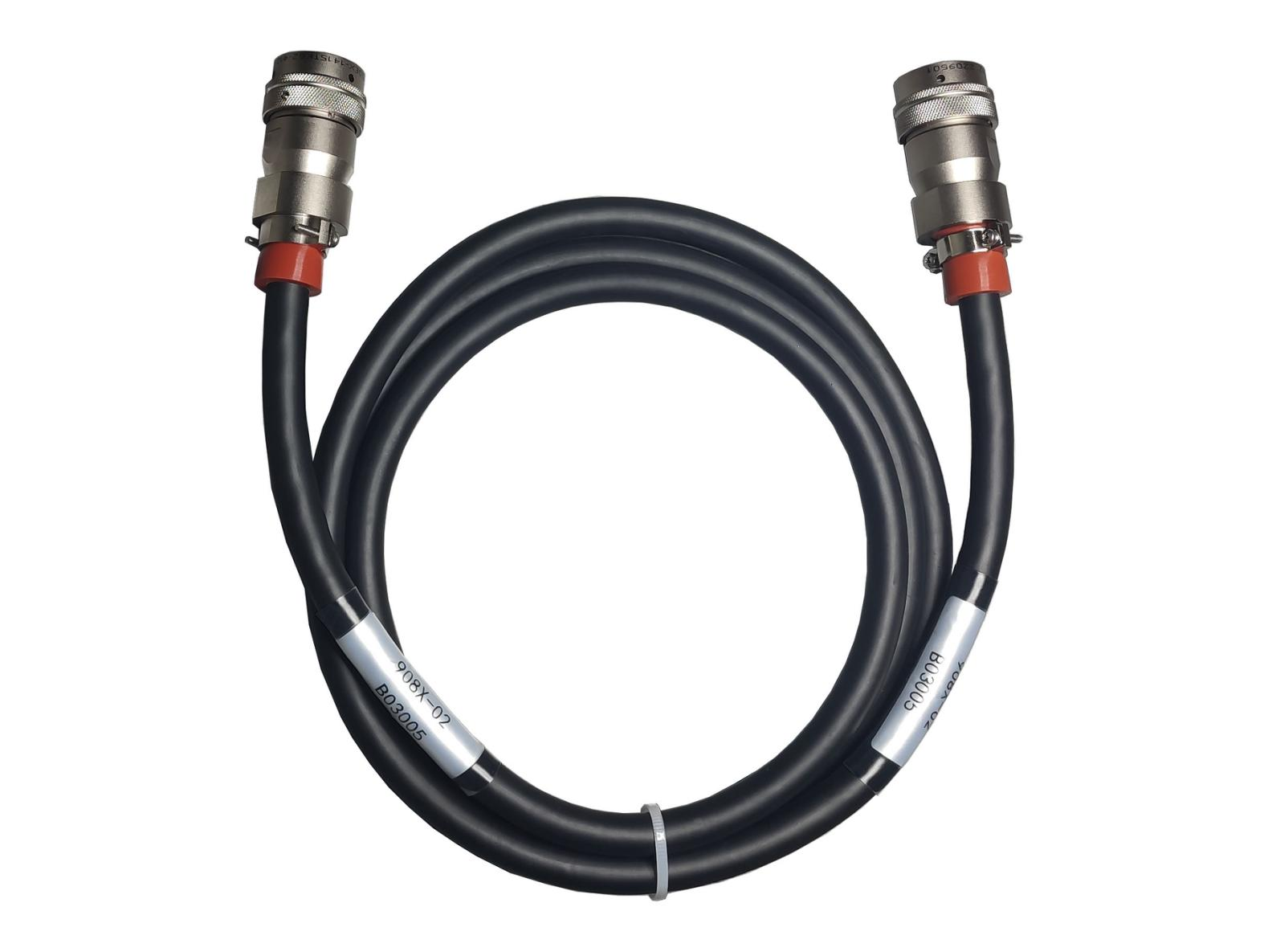
The 9082 cable is a special cable for the FDS Initium data acquisition system, which is used to connect the 9IFC and the FDS host, and can complete the power supply, communication and data transmission of the measurement system. The interface is selected as a circular aviation plug. 9082 Cable Cable can be customized according to the needs of different lengths, the longest optional 100 meters.
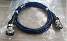
Figure 7 Interface connector 9082 cable
3.7 Scanner cable
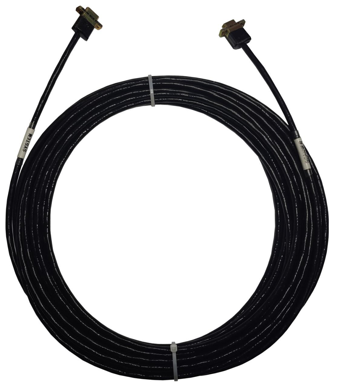
The PSCB scanner cable is used to connect the FDS Initium host machine with the ESP pressure scanner, which is fastened by screw locking. The interface is made of miniature DB15 connector. The cable material is low noise shielded cable to realize the effective transmission of information and data. Ensure the insulation, toughness and strength of the cable in the environmental range of -55℃-150℃; PSCB Cable can be customized in length according to requirements, ranging from 1 foot to 150 feet (45 m).
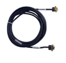
Figure 8 PSCB scanner cable
3.8 Supporting software and driver of the system
PSI Utility Software is a Windows-based application that includes parameter configuration, system calibration, data collection, data logging, data analysis, etc. It also provides convenient program development support, allows users to send and receive specific programming instructions, etc., and provides users with other application routines such as diagnosis and verification. The system can initialize and customize the operation, and can carry out continuous data acquisition, realize real-time numerical display, and the data can be recorded in csv format for analysis and processing in Excel or other software.
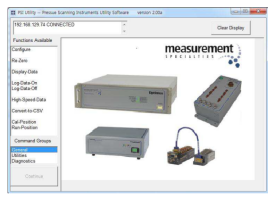
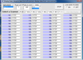
FIG. 9 Operation interface of PSI Utility Software
Ⅳ、Type 9216 electronic pressure scanning valve
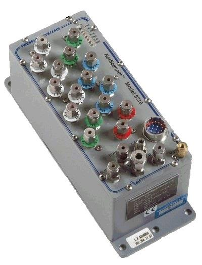
The Model 9216 electronic pressure scanner integrates 16 silicon piezoresistive pressure sensors using the latest microprocessor technology in a compact, rugged package. Each pressure sensor includes a temperature sensor and EEPROM to store calibration data as well as sensor identification information, and the microprocessor uses the data within the EEPROM to correct for sensor offset, range, linearity, and thermal errors. The digital temperature compensation algorithm can reduce the sensor thermal error by a factor of 10 or more.
Figure 10 shows an example of system architecture configuration when multiple 9216s are connected at the same time. The connection required for system operation is extremely simple. Users can obtain power by using the 90DB module, which is connected to the 9216 through 9082 Cable, providing a convenient interface for power regulation, hardware triggers and Ethernet communication.
4.1 9216 electronic pressure scanning valve
Model 9216 electronic pressure scanning valve supports 16 pressure channels; The measurement accuracy of the system (including nonlinear, hysteresis and repeatability errors) was ±0.05% FS. The system test stability was ±0.05% FS. The sampling rate of each channel was adjustable, and the maximum was 500 Hz. The operating temperature of the host is -30 to 80℃, and the storage temperature of the host is -30 to 80℃. Automatically set 10/100 Base-T Ethernet interface; Support TCP/IP, UDP protocol; Instruction trigger, external trigger (TTL level), timing trigger, support PTP time synchronization protocol; The protection level is IP66; The input voltage is 18~36V DC; The external dimensions were 241.3 mm×88.9 mm×89.92 mm.
In this scheme, 8 9216 modules with a range of 250psid are used, with a total of 128 channels. Four 9216 modules with a range of 500psid, a total of 64 channels; Four 9216 modules with 750psi range and 64 channels in total; A total of 16 units 9216, a total of 256 channels.
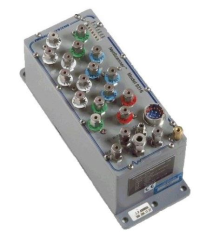
FIG. 10 9216 electronic pressure scanning valve
4.2 9216-HCU heating control unit
9216-HCU (Heater Contol Unit) adopts light weight and good insulation of poly formaldehyde resin shell, internal heating tank and phase change energy storage material + composite heat insulation material several parts.
This combination of heat storage and heat insulation scheme in the low temperature environment, will execute the heat storage material release heat + heat insulation material preservation process; In a high temperature environment, the process of insulation material isolating external heat + heat storage material absorbing heat will be carried out.
When the ambient temperature continues to decrease (-55℃) and the system is not powered, firstly, when the internal temperature of 9216-HCU is lower than the phase change point of the phase change heat storage material, the phase change material begins to release heat, slowing down the temperature reduction trend in the control unit. Secondly, the composite insulation material will effectively isolate the heat radiation and heat convection inside the heating unit and the external environment. The heat conduction process is greatly slowed down to ensure that the temperature gradient inside 9216-HCU is maintained in a reasonable range within a certain time (6 hours), and the equipment cannot be used because of the low temperature of the environment.
When the system is in a high temperature environment (100℃), first of all, the composite insulation material will effectively isolate the heat radiation and heat convection inside the heating unit and the external environment, which will greatly slow down the heat conduction process. Second, if the internal temperature of 9216-HCU is higher than the phase change point of the phase change heat storage material, the phase change material will begin to absorb heat and slow down the temperature rising trend in the control unit. These two processes will effectively ensure that the temperature gradient inside 9216-HCU is maintained within a reasonable range within a certain time (8 hours) to ensure the normal operation of the equipment.
In the case of providing power to the heating control unit of 9216-HCU, when the ambient temperature continues to decrease and the temperature in the heating control unit is lower than the preset temperature, the heating tank starts heating (the preset temperature point is adjustable). When the temperature in the heating tank reaches the preset temperature, the heating is stopped. Phase change materials and heat insulation materials can effectively ensure the slow change of temperature. In the low temperature environment, the 9216-HCU was preheated for 10 minutes before each use of the 9216 pressure scanning valve, and then the pressure measurement operation was started.
9216-HCU host heating control unit 28VDC power supply, maximum working current 1.8A, two-wire power supply, structure diagram as shown in Figure 12, temperature control unit size: length 350mm× width 130mm× height 160mm.
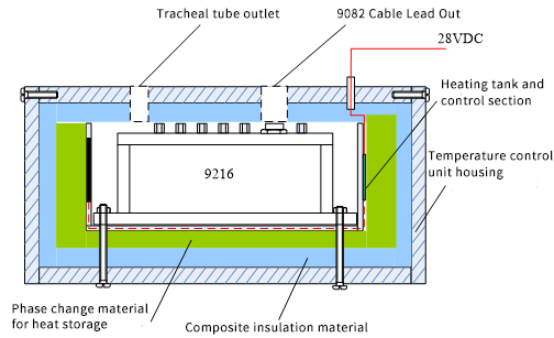
FIG. 11 Structure of the 9216 heating control unit
Ⅴ、Pressure measurement system accessories and system configuration
TE manufactures a wide range of pneumatic accessories for pressure measurement systems that are compatible with ESP series pressure scanners and FDS data acquisition systems, as well as the 9216 electronic scanning valve system. Some of these include:
1. 0.040 inch diameter nylon pipe, 500 ft/roll, 10 rolls
2. 0.063 "diameter nylon pipe, 500 ft/roll, 10 rolls
3. 0.040 inch fixed spring, 500 / package, 5 packages
4. 0.063 inch fixed spring, 500 / package, 5 packages
5. 0.090 inch fixed spring, 50 / bag, 10 bags
6. 0.125 "nylon purge pipe, 500 ft/roll, 1 roll
7. 1/8 "compression fitting nylon tubing, 250 ft/roll, 3 rolls
8. 1/4 "compression fitting nylon tubing, 500 ft/roll, 3 rolls
9. 0.040 to 0.063 inch diameter reducer, 30
10. 0.040 inch diameter T connector, 20 PCS
11. 0.040 inch diameter cross connectors, 20
12. 0.040 inch diameter 8-way connectors, 20
13. 0.063 inch diameter T connector, 20
14. 0.063 "pipe diameter cross connectors, 20
15. 0.063 inch diameter 8-way connectors, 20 PCS
16. Pipe clamp installation tools, 3
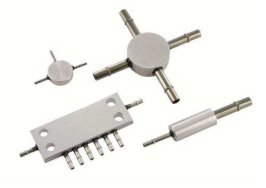

Figure 12 Pressure scanning system accessories


