I. Background
UAV system generally includes vehicle platform, measurement and control and information transmission system (referred to as measurement and control system), mission payload system, ground integrated security system, navigation and flight control system, etc. by function. As an important part of the UAS, the UAV measurement and control system realizes remote control, telemetry, tracking and positioning and information transmission of the UAV, mainly including data chain and ground control station, where the data chain system includes measurement equipment, information transmission equipment, data relay equipment, etc.
The early foreign UAV measurement and control systems were mainly developed independently with the use demand of each military service as the traction, and lacked unified specifications in system system, working frequency band, transmission performance, message format, control protocol, human-machine interface, information processing, information distribution, etc.The development of domestic UAV measurement and control and information transmission system has gone through a course of nearly 20 years, successfully breaking through a series of key technologies such as simultaneous multi-target measurement and control, broadband signal tracking, digital compression of images, aircraft relay and Ku/Ka dual-band satellite relay, integrated display control, miniaturization of airborne equipment, and successfully developed a variety of models of measurement and control data chains and ground command and control stations that basically adapt to the needs of the modern battlefield environment.Through the ground-to-air line-of-sight data chain, aircraft relay data chain or aircraft-to-star-to-ground satellite relay data chain, the integrated functions of mission planning, command and control, remote control, telemetry, tracking and positioning and load data transmission can be realized for different types of UAVs with different purposes.
UAV flight control system generally consists of vertical gyro, three-axis rate gyro, heading, dynamic and static pressure sensors, on-board computer, rudder and other components. During the final assembly and test of the UAV, these devices should be fully tested for function and performance indicators and parameter calibration to ensure that the devices and systems work properly.At present, the simple rotary table is commonly used to apply excitation signals to vertical and rate gyro, and the standard dynamic and static pressure table and manual fine-tuning vacuum pump to apply excitation signals to dynamic and static pressure sensors to detect the work of various sensors and on-board computers, and to calibrate some parameters; the protractor is used to measure the rudder declination of the aircraft, and the inspection report is formed according to the control law and the corresponding judgment. These tests are basically operated manually, and their accuracy is poor and efficiency is low, so it is very necessary to develop an automatic testing system for UAV flight control equipment.
1. System hardware configuration and software design
The sensor on the drone is mostly analog output, while the rudder declination is mechanical angle output, so its detection content is different. In order to meet the demand of automatic detection of flight control equipment, the system is designed based on virtual instrumentation, using PXI bus-based scheme, the system data acquisition, signal conversion, standard signal excitation and state control, etc. The PXI bus modular instrumentation is used, and the system composition Block diagram 1 shows:
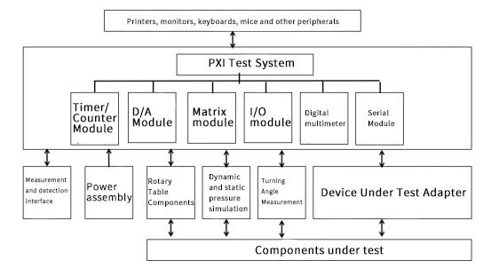
Fig. 1 UAV flight control setup test system composition
1.1 System hardware configuration
(1) measurement and control computer: PXI embedded computer, mainly to complete the PXI instrument modules and testing process control, test program scheduling management, test data recording, storage, printout and so on.
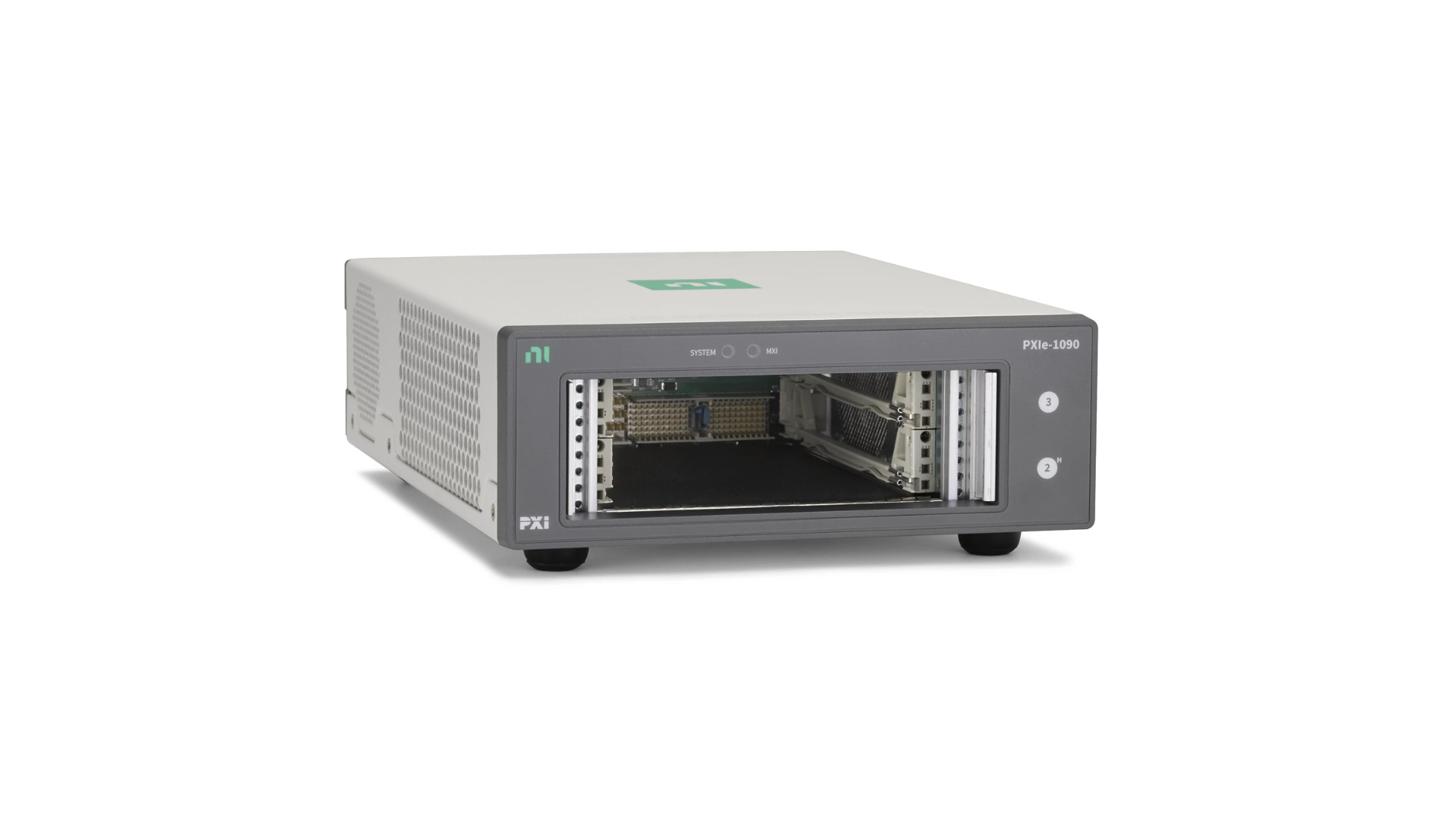
(2) chassis: choose PXI system 13-slot chassis the chassis with overheating, overcurrent, short circuit to ground, power protection and other functions, and electromagnetic compatibility and good ventilation.
(3) turntable components: taking into account the system volume, cost and different models of gyro sensors detection accuracy requirements, choose the accuracy of 0.05 ° / s and with a GPIB interface rate turntable and accuracy of 0.1 ° of the attitude turntable.
(4) dynamic and static pressure simulation: dynamic and static pressure generated by the vacuum pump, and the choice of atmospheric parameters tester for dynamic and static pressure parameters of the calibration, can be programmed by the measurement and control computer operation.
(5) power supply components: the program-controlled multi-channel DC power supply, DC 30V and ± 25V adjustable voltage, the power supply with online monitoring, data readback, self-test function.
(6) rudder angle measurement: select the encoder as a sensor, the mechanical angle quantity is converted into a digital quantity, through the I/O port template input to the PXI system.
(7) measurement detection: the system is designed with measurement detection interface, according to the measurement detection data content, to complete the measurement detection of signal sources, measurement instrument modules.
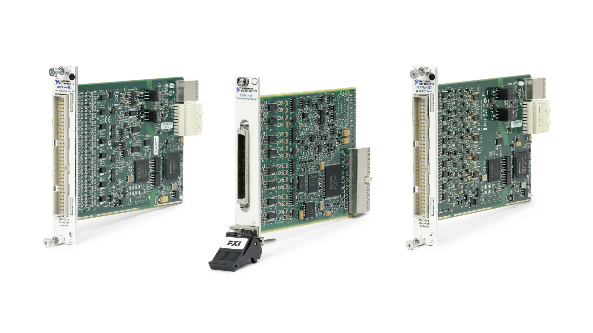
(8) PXI instrumentation modules: considering the need for test accuracy, respectively, selected serial port, short array switch, timing / counting module, D / A module, digital multi-meter module, 96-way high-speed parallel I/O test module, etc.
(9) Adapters: In the development, the signal conditioning, self-testing anti-insertion error, hot-swappable design, etc. are considered to ensure the versatility of the testing system and the ease of operation and the correct and safe connection of the components under test.
2. Detection method
1.2 Gyro and heading sensor detection
The detection principle is shown in Figure 2
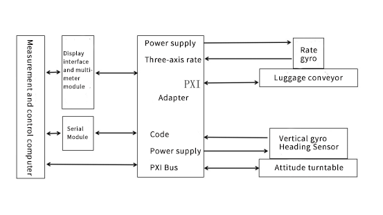
Fig. 2 Schematic diagram of gyro and heading sensor detection
The sensor is placed on the turntable assembly, and the measurement and control computer applies excitation signals to the turntable assembly, and the analog signals from the rate and vertical gyro output and the digital output from the heading sensor enter the detection system through the adapter for acquisition.
2.2 Dynamic and static pressure sensor detection
Detection by the vacuum pump to generate dynamic and static pressure, through the output of the standard dynamic and static pressure signal, the dynamic and static pressure sensor on the UAV and the on-board computer will measure the dynamic and static pressure signal decoded into the flight altitude and airspeed, and through the detection of the serial module to the measurement and control computer, the measurement and control computer will be several groups of standard excitation signal and the sensor measured signal at the same time printout, and through the serial module detection results to the on-board computer for automatic parameter calibration. The dynamic and static pressure detection principle is shown in Figure 3.
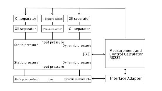
Figure 3 Dynamic and static pressure sensor detection principle diagram
2.3 Onboard computer and rudder deflection function integrated detection
The system applies standard excitation signals to various sensors on the aircraft through the turntable assembly and atmospheric parameter tester, and the on-board computer and various sensors will measure these signals, and the on-board computer will calculate the control amount and output the control signal to the rudder via D/A, and the rudder will drive the aircraft rudder deflection, and the on-board computer will send the digital control amount to the measurement and control computer through the detection serial port, and the system will measure the aircraft rudder deflection, and then it can According to the standard excitation signal, the control performance of the on-board computer and the rudder can be checked. The testing principle is shown in Figure 4.
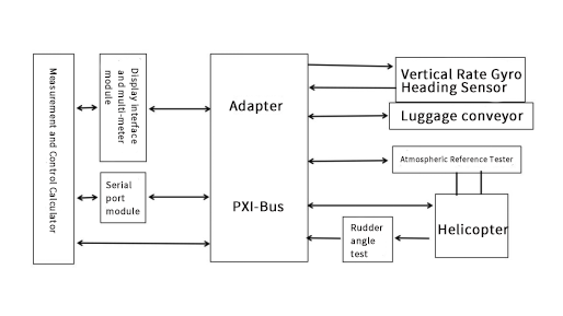
Fig. 4 Schematic diagram of on-board computer and aircraft detection
4. Conclusion
The UAV flight control equipment testing system is an open, integrated and modular system, which can carry out equipment testing and fault diagnosis, as well as the calibration of sensor parameters, with good generality, strong expansion capability, high testing accuracy and automation. With the rapid development of science and technology, new technologies and new products are emerging, the application technology of UAV flight control equipment will also have new breakthroughs and developments. The UAV flight control equipment testing system based on PXI bus technology not only solves the current problem of automatic detection of UAV flight control equipment, but also can be applied to the detection of new flight control equipment by adding the corresponding adapter interface, which has broad application prospects.


