I. Background
Photoelectric pod technology and its pods are an important part of photoelectric reconnaissance warning technology and its equipment, but also the core equipment of UAV reconnaissance, which will fill the role of tactical reconnaissance of specially manned aircraft, for which various countries are vigorously developing various uses of photoelectric pods. Optoelectronic pods can be widely used in land, sea, air and space reconnaissance, and their carriers are vehicles, ships, aircraft and satellites, etc.
Airborne electro-optical pods, usually equipped with forward-looking infrared cameras, television cameras and laser pointer/rangefinder and other electro-optical sensors. According to the function of the main airborne navigation pods and targeting pods two types. With the continuous development of precision-guided weapons technology, airborne electro-optical pods have become an important part of the precision strike system of warplanes.It isolates the impact of attitude change and mechanical vibration of the carrier aircraft on the pointing of the photoelectric sensor, while it uses the photoelectric sensor to complete the search, positioning and tracking of the target. The avionics pod is a system with large time delay, nonlinearity and yet requires high tracking and stability accuracy, which requires high design requirements for the controller.
The optical tracking and measurement pods play an important role in flight testing, as they are mounted on the carrier aircraft, which can monitor and measure the full flight time of the target aircraft in real time by flying with it. Since the flight test itself is very costly, it requires us to ensure that all systems are working properly before the pod is mounted on the aircraft and that each flight is a valid flight. This system realizes an intelligent pod ground inspection system, which uses 220V AC power from the ground and is able to supply power to the pod, and uses a target simulator as an aid to jointly complete all functional inspections of the pod before it is hooked up, and is able to intelligently diagnose and locate faults in the pod and the on-board control equipment.
1.Ground inspection system requirement analysis
The optical pods are powered by 28 V DC and 115 V AC. The DC power supplies the control circuits and each functional module, and the 115 V AC power supplies the servo system, so the ground inspection equipment needs to have the capability to provide 28 V DC and 115 V AC power. The pod also has high-definition, high-speed video tracking storage function, the corresponding ground detection equipment needs to have video reading detection and download capability. At the same time, the pod also has laser ranging, remote control telemetry system, ring control system, etc. Therefore, the ground inspection system must have the corresponding control program to detect the parameters of the corresponding system. This program controls the work of the pod through PXIe bus interface, and detects all functions of the pod through the software of each function acquisition module designed on the ground control computer.
2. Overall system structure design
In order to facilitate the installation and commissioning of the system, all components of the ground testing equipment are integrated in a standard cabinet, driven by a four-wheeled cart with brakes, see Figure 1.
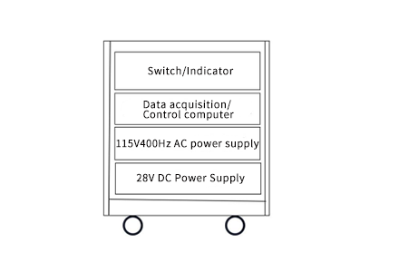
Fig. 1 Schematic diagram of system components
The system includes data acquisition and control computer, switch/indicator surface, monitor, keyboard and mouse, connection socket, and power supply. Among them:
1) switch/indicator panel including power switch, power and status indicators, etc., and signal conditioning box behind the panel (including connection cables, signal conditioning board, etc.).
2) control computer plus related data acquisition module, with the test software, to complete the test work, it is the core of the whole system.
3) 28 V DC power supply (DC) and 115 V 400 Hz AC power supply (AC) using two independent power supplies, with over-current and overvoltage protection functions.
3. Ground detection system interface design and circuit design
The ground detection equipment supplies power to the pod, and then detects all the signals to be tested in the start-up and normal operation of the pod, and manipulates all the functions of the pod through PXIe bus, and the electrical interface is shown in Figure 2. Among them:
1) No.1 socket, complete the detection of all video signals (image transmission signals), 1-channel PAL video signals.
2) No. 2 socket, complete the detection of pod A/D signal, I/O signal, resistor resistance and 4-way RS422 signal.
3) No. 3 socket, complete the power supply and RS422 communication detection of on-board control equipment, relay 1 control target simulator and power supply of on-board control equipment.
4) No. 4 socket, to complete 1 RS422 communication detection and 2 power supply control of the pod, where relay 2 is responsible for the 28 V DC power supply control of the pod,
and relay 3 is responsible for the 115 V AC power supply control of the pod.
5) No. 5 socket, input 220 V AC power, output power supply to the testing equipment and the pod.
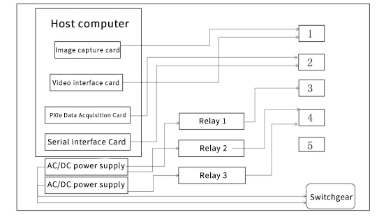
Figure 2 Schematic diagram of the electrical interface of the ground testing equipment
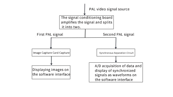
Fig. 3 Schematic diagram of PAL signal detection
No. 1 socket image acquisition card acquisition of PAL video signals from the signal conditioning board is amplified by the first of the two video signals, the other video signal is used to test the software to analyze the image quality. Specific video signal detection schematic diagram shown in Figure 3, which separates the output of the circuit synchronization signal through the A/D acquisition card acquisition, the software interface in the form of a waveform display, you can judge the synchronization signal based on the waveform.
4. Software Design
The "pod ground testing software" is a special software running on the test equipment, and its main role is to help the testers accurately, conveniently and quickly complete the test task. According to the needs of the project, the software can not only test and debug the pods, but also has the function of system fault diagnosis, so the software design focuses on the consideration of the generality of the requirements of the software architecture as shown in Figure 4.
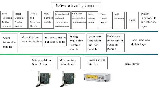
Figure 4 Software Hierarchy Diagram
Based on the above architecture model, the main functions to be achieved by the application software are as follows:
a:system self-test; b:power control; c:health management; d:pod control, test and display; e:pod fault diagnosis; f:ground control equipment communication test and display;
g:on-board control equipment communication test and display.
The software adopts modular structure design, the management software is called by the user or the system manager, and the test software is called by the management software,
both can be re-entered, as shown in Figure 5.
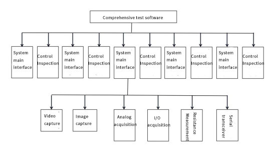
Figure 5 Software Composition Structure
The basic function module mainly realizes the functions of serial port, video and analog acquisition, etc. It provides the system function modules with the formation of API functions to call, which realizes the layered architecture of the software.
1) The serial module provides API functions to realize the setting of communication baud rate, serial output buffer.
2) Zone setting, serial input buffer setting, serial transceiver and other functions.
3) Resistance measurement module provides API functions to realize the resistance measurement of any channel and configuration of measurement parameters.
4) The voltage measurement module provides API functions to complete the voltage measurement and configuration of measurement parameters for any channel.
5) Image acquisition module provides API functions to complete the configuration of parameters and realize the acquisition of video signals.
6) The video acquisition module provides API functions to realize the acquisition of PAL video signals.
7) discrete input/output measurement module provides API functions to complete the configuration of parameters and data acquisition.
8) Power control module provides API functions to realize the control of power supply.
The software shows the test process in graphical or tabular form, allowing the user to operate the test process and realize the data recording and display of the test process,
as well as the operation of start, stop, pause and single step of the test process.
The signal sources and interface channels are combined and configured in a certain timing relationship to provide various test excitations to the part under test, and then
complete the system test.
According to the types of faults in the pods, the test process of fault detection is established separately, and the detection and diagnosis process of each fault is realized by the software as shown in Figure 6.
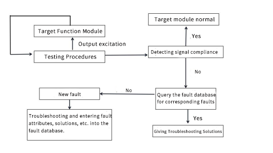
Fig. 6 Fault diagnosis module program flow chart
The method of collecting feedback information from the pods by giving them an output excitation detects whether the signal is within the specified range or whether
the desired effect is achieved.
For each fault, a set of test procedure and test interface is designed, and the fault information is recorded into the database.
After storing the common fault phenomena in the database, i.e., the cause of the fault can be found and analyzed by keywords. New fault phenomena are stored in
the database during the testing process to enrich the content of the fault database.
5 Conclusion
This paper designs and implements a set of intelligent ground inspection system for a certain type of photoelectric pod before hanging the loader. The ground inspection system can quickly and intelligently detect the functions of the target pod, and can quickly give the cause of the failure and its solution for the detected module failure. At present, the system has been well applied in practice, which has strongly guaranteed the scientific test flight mission.


